|
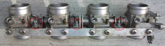
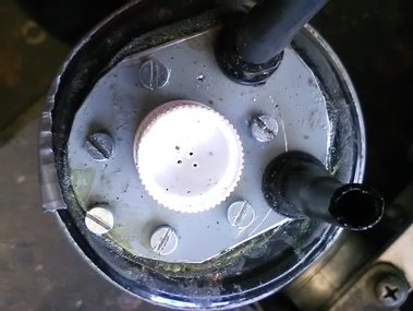
The throttle valves are linked and the linkages are adjustable - screws and lock nuts ringed in the image.
The books tell you, never touch those. It's not complete rubbish. If you fiddle with them I doubt you'll ever get them near in-sync unless you remove the TB assembly and have access to an air flow meter or similar. This post is about the "or similar" |
My motor now idles nicely at below 1000 rpm and at just over 1000 when warm. No more 1700 rpm that cannot be adjusted down.
From the beginning I suspected that the too-fast idle was caused by the throttle valves not closing properly. The accelerator & fast idle cables were disconnected, TPS removed – all the common reasons for not closing had been eliminated. Adjusting the between-TB linkages while running the engine did not fix this - although the TBs were in sync it seemed that they were still not closing.
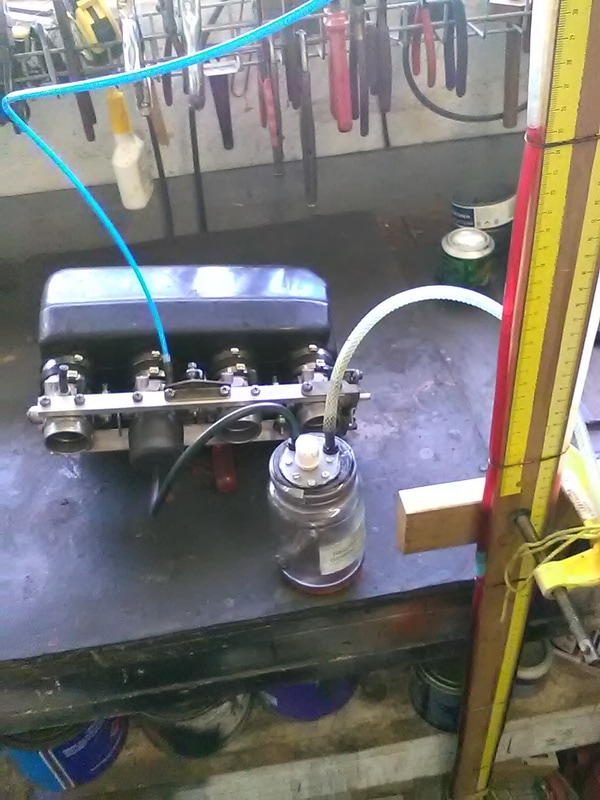
I removed the TB assembly. I adjusted the linkage between TB3 & TB4 so TB3 was in its most open position relative to TB4. I repeated this for the other linkages, TB2 open relative to TB3 and TB1 open relative to TB2. In effect TB4 valve was now shut and the others in varying degrees of open.
Using a strip of audio magnetic tape as a "feeler gauge" I adjusted the center stop screw so TB4 throttle valve was just closed – a distinct drag on the tape/”feeler gauge”. Leaving the stop screw in that position I adjusted the 3 linkages so TB3, TB2 and TB1 butterfly valves offered the same resistance to pulling the "feeler gauge" out as TB4.
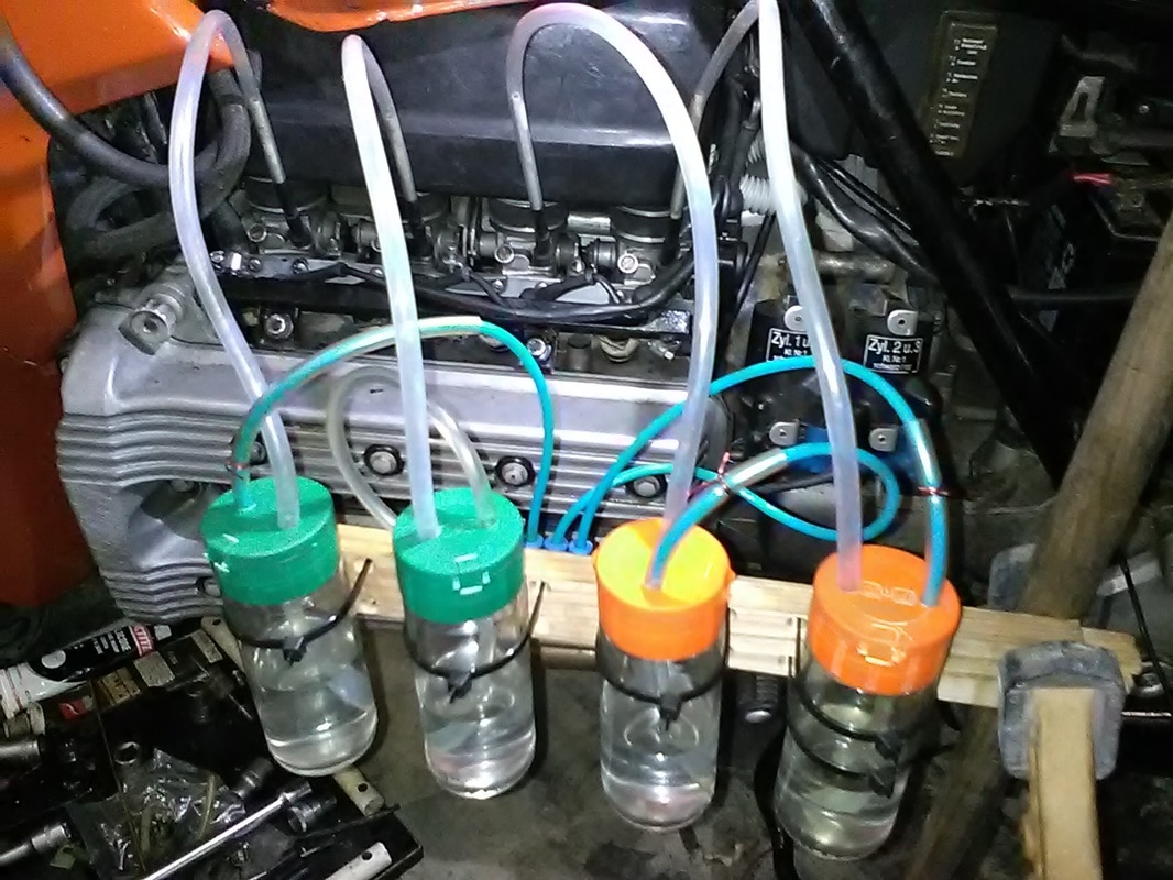
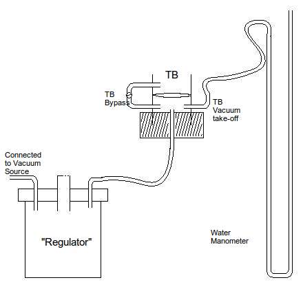
The throttle valves were now physically synced as good as I could get them. In order to fine tune this static sync at the closed position I cobbled together a tester, a process to test the “vacuum” each throttle valve can hold against the same negative pressure applied. The sketch below illustrates the principle.
From the beginning I suspected that the too-fast idle was caused by the throttle valves not closing properly. The accelerator & fast idle cables were disconnected, TPS removed – all the common reasons for not closing had been eliminated. Adjusting the between-TB linkages while running the engine did not fix this - although the TBs were in sync it seemed that they were still not closing.
I removed the TB assembly. I adjusted the linkage between TB3 & TB4 so TB3 was in its most open position relative to TB4. I repeated this for the other linkages, TB2 open relative to TB3 and TB1 open relative to TB2. In effect TB4 valve was now shut and the others in varying degrees of open.
Using a strip of audio magnetic tape as a "feeler gauge" I adjusted the center stop screw so TB4 throttle valve was just closed – a distinct drag on the tape/”feeler gauge”. Leaving the stop screw in that position I adjusted the 3 linkages so TB3, TB2 and TB1 butterfly valves offered the same resistance to pulling the "feeler gauge" out as TB4.
The throttle valves were now physically synced as good as I could get them. In order to fine tune this static sync at the closed position I cobbled together a tester, a process to test the “vacuum” each throttle valve can hold against the same negative pressure applied. The sketch below illustrates the principle.
The principle
Measure the Vacuum of Each TB
The principle is to measure the vacuum with the throttle valve closed for each TB and then make adjustments until all TBs are the same.
The vacuum source can be a vacuum cleaner or the sucking end of your compressor. The regulator prevents the water being sucked out of the manometer. Depending on the vacuum source it may not be required. |
Water Manomater
It took me about 4 iterations of making inter-TB linkage adjustments and they were balanced. Readings on the manometer were between 215mm and 225mm.
|
Regulator
Just a glass jar. I drilled tiy holes in the lid to adjust the maximum "vacuum" to about 1 meter of water
Final Balancing