Bent Frame Straightened
In this topic I cover what worked for me in straightening the frame of the accident damaged K100 I bought. The frame was twisted; the right front frame arm was sheered off, it looked like a fatigue fracture; the left front arm was bent in; the part of the engine casing where the left arm bolts on was broken off.
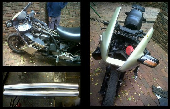
Images show some of the damage. The fairing components, lights, mirrors, cosmetic stuff were all smashed. My major concern was structure damage-twisted frame, right front frame arm sheered and the left front frame mounting lug on the casing broken. Fortunately it had not broken through the casing. The reason for thinking the sheer is a fatigue break is because there was no bend in the frame arm. On the other hand, the left side frame arm, the one associated with the casing break was bent.
Wheel alignment was all over the place. Back-to-front alignment was out by about 30mm and the wheel planes, angle between horizontal and wheel plane, differed by several degrees.
Wheel alignment was all over the place. Back-to-front alignment was out by about 30mm and the wheel planes, angle between horizontal and wheel plane, differed by several degrees.
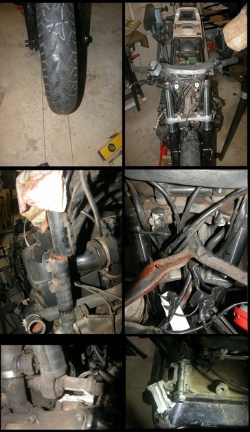
The top two images in the collection on the left show the misalignment and twist. I strung lines from the back wheel to the front of the bike, each line just touching the back wheel sides and extending forward to beyond the front wheel. Notice that the front wheel is sitting on the left side line instead of centred between the lines. Notice the angle of the forks relative to the rear cowl which I had levelled by using a spirit level.
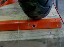
Notice the broken RH frame arm top section is misaligned with the bottom stub still attached to the engine casing. I saw no bending. The misalignment I guessed was due to frame twist and if I took the twist out, the two stubs would align. This turned out to be a correct assumption.
The bottom images show the engine casing break.
The plan: Get the twist out first. My assessment of the damage was that the twist is the primary cause of wheel misalignment. Assuming I get the twist out and the wheel alignment is okay, I would then do whatever bending needs to be done to get the left front arm of the frame aligned with its mounting position on the engine casting and then have the casing welded. I would then reassemble the frame and drive train, fastening all the mounting points except for the still broken right front frame arm. Check the wheel alignment again. Finally do whatever bending needed to be done to the right frame arm stub, if required, make an insert and tack weld it in position. Then the frame would go back for welding that break.
My frame straightening rig is shown in the photos below. The main components are a C-channel bolted to the floor to which I bolt the back of the bike frame, a 40 mm pipe frame lug-bolted to the floor that serves as anchor for my pulling jigs and a "koevoet", a sturdy crowbar that goes through the steering head. I made inserts to prevent the crowbar from touching the steering head races.
I added some braces to make sure my rig is sturdy, two braces from the top of the pipe frame down to the C-channel and one that I could use to brace either of the two diagonals of the pipe frame.
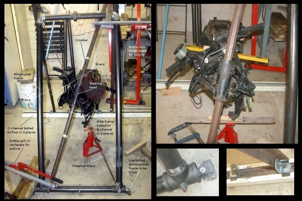
This is not engineering, not even like blacksmithing-it's trial and error stuff. You cant measure how far to bend the frame, because it is going to spring back. Notice in the photos above that the steering head is bent to about 20 degrees relative to the upright of the pipe frame. The accident twist was less than 5 degrees in the opposite direction. As it turned out this 20 degree bending was a little too much and I had to bend it back a little. You have to bend, fit it back on the drive train, measure. Then put it back in the bending jig, bend again ..... I went back and forth maybe 5 or 6 times. The 5 or 6 times included the trial and error straightening the LH frame arm.
I don't have photos of that bending operation. I did it by holding the steering head in the vertical position, clamping the crowbar with two long bar clamps. I then bolted a 40mm pipe to the bottom of the LH frame arm. The bike frame was now held firmly in four points, back frame arms to the C-channel and top and bottom of the steering head by means of the crowbar and the protective inserts in the steering head. I inserted a wooden block between the frame and an the 40mm pipe and pulled the top of the pipe with my hydraulic jack puller arrangement.
Although I was tempted at times to use heat, all the bending was done cold. I figured if I heat up a section of the bike frame, that's where it will bend and that seemed not right to me. I may have ended up with all the frame mounting points in the correct position, but it made more sense to me to try do the reverse of what happened in the accident; a car hit the bike on the RH side of the front end. The impact was against the forks which were bent some and the rest of the impact energy went via the steering head into twisting the frame.
August 8, 2013
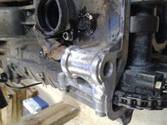
It looks good. The welder told me the casing will break in 100 other places before that weld gives way.
It looks good. The welder told me the casing will break in 100 other places before that weld gives way.
May 10, 2015
I'm slowly putting it together. The wheel alignment is within tolerance. The final assessment will be when I ride it.
I'm slowly putting it together. The wheel alignment is within tolerance. The final assessment will be when I ride it.
